Wiring a Freshly Imported JDM 100 Series Land Cruiser for a scheel-mann Heated Seat Swap

A field-verified reference for the driver and passenger seat harnesses on a 2001 JDM UZJ100, built from a 2UZ-FE automatic with the camper package.

Why This Article Exists
The 25-year import rule has only recently made JDM 100/105 Series Land Cruisers legal to bring into the United States. Toyota's own TIS (Technical Information System) covers North America-market vehicles only, since a JDM VIN won't resolve in it: these trucks never passed through Toyota's North American distribution network in the first place. The closest public equivalent is Toyota's "Overseas Customer Service Technical Division" manual (covering UZJ100, FZJ100/105, HDJ100, and HZJ105 across export/RHD markets), which is extensive but not identical to genuine Japan-domestic documentation.
This article documents what was actually verified on a JDM 2001 UZJ100's driver and passenger seat harnesses, while converting from the factory Toyota seat heaters to scheel-mann seat's own heating elements. Nothing here is inferred from a diagram alone: every pin function was traced on the physical harness.
Vehicle & Trim
Chassis: UZJ100 (2UZ-FE 4.7L V8), automatic transmission
Model year: 2001
Configuration: RHD, camper package, JDM (Japanese domestic market)
Seat equipment on this trim: manual seats with factory seat heaters on both sides. No power seat track. Driver side does has a single bolster/lumbar motor; passenger side has none. No driver seat position sensor was identified on this vehicle. Passenger side has an occupant classification (OCS) pressure pad; driver side does not.
Toyota's own parts nomenclature uses vehicle-absolute LH/RH, not driver/passenger. On a RHD JDM truck, the passenger seat sits on the vehicle's left side, so parts catalogued as "LH" are the passenger-side parts, and "RH" parts are the driver's.
Part 1: The Passenger Seat Harness

Identifying the Harness

The passenger seat wire harness carries Toyota part number 82192-60060, officially "WIRE, FRONT SEAT, LH," the アリ(シートヒータ) ("with seat heater") variant, catalogued for 01/1998-08/2002 production, confirmed directly from a parts-catalog lookup against the physical tag on the harness. The non-heated equivalent is 82192-60020. Both share the same base harness design; the heated version adds the heater circuit wiring.
The Main Connector
The large connector at the end of the main trunk is an 11-pin Yazaki housing, confirmed by physical comparison against our existing shop's stock. It's the same connector family used across other Toyota 100-series applications.

Only 4 of the 11 available positions are populated on this trim.
Passenger 11-Pin Connector Pinout
Wire | Function | How it was confirmed |
W/B | Shared ground/common | Continuity traced to both the heater circuit and the OCS/buckle loop return |
R/L | Heater, high | Continuity traced exclusively to the 3-pin heater connector |
B/L | Heater, low | Continuity traced exclusively to the 3-pin heater connector |
Green | OCS/buckle loop feed | Continuity traced to one of the two 2-pin loop connectors, returning via the shared W/B ground |
The W/B wire is doing double duty: it's not "the heater's ground," it's the ground everything downstream shares, including the seatbelt/OCS loop.
The Heater Circuit

The 3-pin connector serving the heater is a Yazaki. It carries the three heater wires above and feeds a Y-cable to two heating zones, an upper pad (backrest) and a lower pad (cushion), wired in parallel, not independently switched. Both pads always run at whatever level the switch selects; there's no separate zone control.
The OCS / Seatbelt Buckle Loop
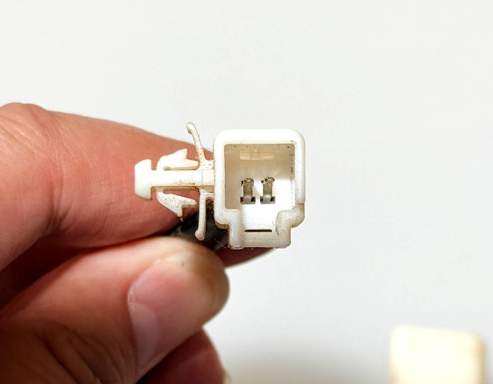
The Green wire and the shared W/B ground form a second, independent loop through two small 2-pin connectors wired in series, but one signal that only reads continuous when both devices are in their "closed" state simultaneously.
One connector (square) is the seatbelt buckle switch.
The other is for the passenger OCS pressure pad.

Both connectors are 2-pin Yazaki housings, but without the polarization keying tab present on our shop's existing 2-pin Yazaki stock. Since pin count, pitch, and contact size all match, the resolution was to trim the keying tab off the in-stock part rather than source an exact-variant replacement. We have since sourced the correct connector.
Given that the passenger OCS pad is a safety-relevant occupant-classification/SRS component, it is being retained and relocated into the scheel-mann seat cushion by the customer, following our previous pressure pad article, instead of shipping to Tolerance Stack to install into the seat before shipping.
Part 2: The Driver Seat Harness

Identifying the Harness
The driver seat harness carries Toyota part number 82191-60030F, read directly off the physical harness tag. Following the same LH/RH numbering pattern as the passenger side (82192-6xxxx), this is inferred to be "WIRE, FRONT SEAT, RH," the driver-side counterpart.
The Main Connector
Same connector family as passenger: an 11-pin Yazaki housing, physically matching the passenger side. This trim populates 5 of the 11 positions, one more than passenger, consistent with the driver side carrying an extra circuit (the lumbar motor) that passenger doesn't have.
Driver 11-Pin Connector Pinout

Wire | Function | How it was confirmed |
W/B | Shared ground/common | Traced to the heater circuit, the motor control junction, and the buckle switch: a single ground daisy-chains through all three branches from one shared pin |
R/L | Heater, high | Continuity traced exclusively to the 3-pin heater connector |
B/L | Heater, low | Continuity traced exclusively to the 3-pin heater connector |
Red | Motor circuit power | Traced to the 4-pin control junction connector |
Green | Buckle switch feed | Traced to a square 2-pin connector, standalone, not part of a series loop the way passenger's is, since there's no OCS pad on this side to chain it with |
The Heater Circuit
The driver's 3-pin heater connector carries the exact same embossed "11763" marking as the passenger connector, and continuity confirms the same R/L (high), B/L (low), W/B (ground) roles. Functionally, this is the same part.
One data point from tracing is worth a note for anyone reading this: continuity showed B/L bridging to both B/L and R/L on this connector, while R/L only bridged to itself. With the factory pad still attached at the time of that test, the most likely explanation is the pad's internal resistive element connecting the two taps. It's also moot for this build regardless of cause, since the factory pad is being removed entirely as part of the scheel-mann swap.
The Lumbar Motor Circuit

A 4-pin connector carries Red (power) and W/B (ground) directly from the 11-pin connector, plus a Blue/Red and Blue/White reversible-polarity pair that feeds a separate gray 2-pin connector, confirmed by the customer to be the lumbar motor. The 4-pin connector's role as a control/junction point (rather than the motor itself) is a reasonable inference from the wiring pattern: a dedicated power/ground pair driving a second connector with a reversible pair is consistent with a simple reversible DC motor circuit, but hasn't been independently bench-tested beyond confirming all four pins trace where expected.

This circuit is being left unused and capped off for this build, since the customer isn't using the lumbar function on the scheel-mann seats. Exposed terminals on both the 4-pin and gray connectors should be capped or heat-shrunk regardless, since an unused 12V-capable circuit left bare in a seat is an avoidable short risk.
The Seatbelt Buckle Switch
A small square 2-pin connector carries Green (dedicated feed) and W/B (shared ground). Unlike the passenger side, this isn't part of a series loop: there's no OCS pad on the driver's seat to chain it with, so this is simply the driver's own seatbelt buckle switch, a plain two-wire circuit.
Part 3: Adapting to scheel-mann Heaters
Why a Direct Swap Doesn't Work
The factory heater pad achieves two heat levels through its own internal construction: the heater circuit provides different effective resistance depending on which switch output is selected, and the switch selects the corresponding circuit. scheel-mann's heating elements, by contrast, are ordinary two-wire resistive pads with no internal tap; each pad (upper and lower) has its own simple 2-pin connector, one red lead, one black. Wiring both switch legs into a plain two-wire pad gives exactly one heat level (both "Hi" and "Lo" deliver full power), not two.
The Series/Parallel Approach That Was Rejected
A resistor-free "series for Lo, parallel for Hi" scheme was considered, since it's a real technique used elsewhere for exactly this kind of problem. It doesn't work here, though, noting: with only three wires (Hi, Lo, common) and two independent pads, the only way to jumper them into a series/parallel arrangement puts the pads in series on Hi (dim, backwards from what's needed) and energizes only one pad on Lo (the other stays dark). Genuine series/parallel switching needs a relay or an additional switch pole to actually reconfigure the connections mid-operation; it isn't achievable with three fixed wires and no moving parts.
The Circuit That Was Chosen

A dropping resistor placed in series on the B/L (Lo) leg only recovers a genuine second heat level. Because R/L and B/L are never energized simultaneously by the switch, the resistor has zero effect on the Hi setting and only ever throttles Lo. Both pads remain wired in parallel downstream, matching the original design's behavior.
This is built as a direct-wire circuit with no relay, consistent with Tolerance Stack's track record across multiple prior 100-series installs at this same current draw, with no issues observed.
Sizing the Resistor: From Formula to Confirmed Number
The sizing formula (R_drop = R_combined x 0.414 for roughly half power on Lo) is only as good as the resistance value fed into it.
Measured: both scheel-mann pads together draw 5A at Hi, at a nominal 12V.
Since both pads sit in parallel, this measurement already is the combined resistance, no need to separately measure one pad and divide by two. R_combined = V / I = 12 / 5 = 2.4 ohms
Dropping resistor calculated for approximately half-power on Lo under the measured 12V/5A load condition: R_drop = R_combined × 0.414 = 1.0 ohm.
Sanity check: At the nominal 12V calculation point, total circuit resistance is 1.0 + 2.4 = 3.4 ohms, giving roughly 3.5A and roughly 30W delivered to the pads, compared with approximately 60W calculated at the measured Hi load. The math is internally consistent, and the Hi-side prediction (12V / 2.4 ohms = 5A) matches the actual measurement exactly.
Resistor dissipation at Lo is approximately 12 to 14W under the nominal 12V calculation condition. The selected resistor is rated at 25 to 50W, providing substantial power-rating margin, but the manufacturer's temperature/derating specifications still govern the permissible continuous operating temperature.
Confirmed final spec: 1.0 ohm, 25 to 50W. This value applies to both the passenger and driver bridge harnesses, since both use the identical heater connector and circuit.
Sourcing the Right Part

The correct part is an aluminum-housed, chassis-mount wirewound resistor: physically a cylindrical body with flat solder-lug terminals on each end and a mounting foot for bolting to metal.
These use solder-lug terminals, not screw terminals as we first hoped from a generic-looking product photo, an assumption corrected by pulling the manufacturer's actual datasheet. The housing itself is anodized aluminum, which is a genuine electrical insulator; the exterior of the part is not electrically live, only the two lugs and the wire immediately attached to them are.
Physical Assembly

Strip roughly 3/8 inch of insulation, then twist the exposed strands into a single tight bundle before doing anything else.
Wrap the wire around the hook in the direction that tightens under tension, not the direction that unwinds it, three-quarters to a full turn, then crimp it down mechanically with pliers so the joint is self-supporting before any heat touches it. The wrap should hold on its own; solder makes it electrically solid rather than being the only thing holding it together.
Solder the joint, feeding solder in so it wicks into the wrap rather than sitting as a blob on top.
Each lug takes one wire, not two. Where a second wire needs to continue on from the same point, it joins a few inches downstream at a proper twisted splice, away from the heat the resistor generates in operation, rather than forcing two conductors into one small hook.
Slide heat-shrink tubing onto the wire before soldering, then after the joint is made, position it to cover the entire exposed lug, from where the wire enters back to where the lug exits the resistor body, and shrink it down snug. For the downstream splice, use adhesive-lined heat-shrink, since that joint has insulation ending on both sides rather than just one.
The resistor's anodized body and its mounting hardware are left completely bare, no wrap over the body itself. Heat-shrink is a thermal insulator; wrapping the heat-generating part of the assembly traps heat against it instead of letting it dissipate, which would work directly against the reason for adding a metal mass in the first place.
Leave a genuine straight run of wire, roughly 1/4 to 3/8 inch, between the solder joint and wherever the wire first bends, with a gentle curve rather than a sharp kink at that bend. Bending immediately at a solder joint concentrates vibration stress at the exact point least able to handle it.
Optional belt-and-suspenders measure: a small dab of high-temp dielectric silicone at the lug-to-body transition seam, guarding against a stray strand of wire bridging that point during vibration. Not required if the heat-shrink coverage is done correctly, but cheap insurance.
The Mounting Block
3D printing the thermal mass first for testing a small batch of aluminum thermall masses were made for the final install
Why not just bolt it to the seat frame: the seat rides on a slider mechanism. A bracket fixed to the seat's stationary mount point would leave the resistor behind the moment the seat moves; the harness (and the resistor riding on it) needs to travel with the seat, not stay fixed to something the seat travels away from.
The solution: a free-floating aluminum block, sized to give the resistor real thermal mass (as required per it's own specs) and exposed surface area without needing to be bolted to vehicle structure at all. The resistor's datasheet specifies its power rating under defined mounting and thermal conditions. The aluminum block is used to provide additional thermal mass and exposed surface area, but it should not be treated as a substitute for the manufacturer's thermal derating requirements. We have a feeling some may look at the prototype 3D printed part and feel that would be adequate, but aluminum is roughly 1000x more efficient for thermal dispersion vs plastics (especially this PETG-HF). The block's two mounting holes are positioned to match the resistor's actual hardware, measured directly off the physical part: 0.75 inches apart along the body's length and 0.80 inches apart across it, a genuine diagonal relationship rather than a straight line. Both holes share a single mounting plane, so the resistor bolts flat to one face of the block despite the diagonal offset. Although it didn't happen on this batch of mounting blocks, future blocks will be pre-tapped to #4-40 threads.
Final block spec:
Aluminum, 3.2" x 1.2" x 0.25"
Two mounting holes, 0.125" diameter, at the measured diagonal spacing above
Four rectangular zip-tie slots, 0.2" x 0.08", arranged in two pairs, one near each end, sized to pass a zip tie in one slot and out the other to capture the wire bundle
Two 3/16"" notches centered on the long edges, for a separate zip tie to wrap fully around the block for a hard mount, independent of the bundle-capture slots
Real straight-line clearance between each resistor lug and the nearest zip-tie slot, so the wire has room for a genuine straight run and a gentle bend before reaching its strain-relief point, rather than flexing right at the solder joint
Manufactured as a flat laser-cut profile, since the design has no features that require milling
Proof 3D-printed in plastic first, verified against the physical resistor, then cut in aluminum
Bridge Harness Bill of Materials
Since both seats' heater connectors are the same part with the same pinout, both bridge harnesses are electrically identical; this table covers both.
Why are we making this info so freely available? Because the chances of us seeing another customer for this model/year JDM100 also wanting scheel-mann seats is likely very very low. So if someone's internet search down the road happens upon this article, maybe it will help them. Or they can skip it all and just get the harness from us ;)
Location | Part |
Seat-harness side | Yazaki 090IIU-3S-1 housing (female) |
Seat-harness side | Yazaki 090IIU-pin-2 terminals |
Inline, B/L leg only | 1.0 ohm chassis-mount resistor, 25W minimum; Ohmite HS25, Riedon UAL25, or Stackpole KAL25 are suitable examples |
Inline, B/L leg only | Aluminum mounting block (custom, see above) |
scheel-mann side (x2, one per pad) | TE MQS housing 1-1718346-1 |
scheel-mann side (x2, one per pad) | TE MQS contacts 5-963715-1 |
Each scheel-mann heater pad terminates in its own TE Connectivity MQS 3-position connector, with only 2 of the 3 positions populated (red, black).

Both bridge harnesses, driver and passenger, have been built to this specification and bench-tested for continuity and resistance, verifying the wiring and calculated circuit behavior before installation.
#LandCruiser #ToyotaLandCruiser #LC100 #UZJ100 #100Series #JDM #JDMImport #25YearRule #RHD #scheelmannusa #HeatedSeats #SeatSwap #SeatUpgrade #ToleranceStack #WiringHarness #AutomotiveWiring #CustomWiring #WiringDiagram #AutoElectrical #DIYAutomotive #CarBuild #VehicleBuild #Overlanding #OffRoad #4x4 #ImportCar #AutomotiveEngineering


Comments