A seat gets disassembled: Part 2- Lets learn together what is inside a 2021 LX570 passenger seat bottom


In Part 1, Kohl's original Lexus LX570 seats showed up at the shop, shipped from North Carolina so we could figure out what a real conversion kit would actually require. To be clear about what that means before we go any further, his original seats are not going back into the truck. Realistically they're headed for the landfill, the same as nearly every factory seat that gets pulled for THIS kind of conversion. That's not a sentimental loss so much as a practical reality of how this work goes.
What we're actually attempting is something more specific than that. We're taking the rails, the motors, the sensors, and the harnesses out of these factory seats, the parts that already work and already fit the truck, and carrying them forward POTENTIALLY into a newly developed scheel-mann mounting kit paired with a Vario F seat. The airbag is not part of that plan. It is not going back in, full stop, no caveats. Everything else in this teardown is in service of figuring out exactly which pieces survive that transition and which ones don't.
That's the goal, laid out as clearly as we can lay it out right now. This part of the write-up is about taking the seat bottom apart to find out what's actually in there to work with, piece by piece, in the order we actually encountered it and how the motors interact with the seat rail.
A scope note before we get into it. This write-up covers the seat bottom only, the cushion and everything underneath it. The seatback is its own animal and we haven't gotten into it yet, partly because the bottom alone turned out to be enough to chew on for one stage of the project. That's not an arbitrary stopping point either. It's where the bottom assembly naturally ends and the seatback assembly begins, and it happens to land at a convenient place to pause anyway, which we'll get to by the end of this.
One more thing worth saying up front, because it shapes how the rest of this reads. This isn't a finished teardown written up after the fact, polished into a tidy narrative once we already knew how the story ended. We're documenting this as it happens, including the parts we don't have answered yet and the parts we're still a little uneasy about. The electrical side of this project, the connectors and motors and what they actually do, is currently further along than the mechanical side. We didn't even know how the seatback separates from the base when this stage of the work started. So treat this as a progress report from partway through the job, not a victory lap after it's done. If that means some of what follows reads as us figuring things out in real time, that's because we are.
Short tool list
Here's the entire tool list required to get through everything below: a JIS driver, a 12mm socket, and a pair of diagonal cutters (and maybe a pick tool).
That's it. No specialty tools, nothing you'd need to special order from a dealer parts counter or wait a week for from Amazon. If you're the kind of person who looks at a teardown video and immediately starts mentally tallying up what it's going to cost you in tools before you've even touched the first bolt, the answer here is almost nothing.
That's worth sitting with for a second, because it says something about where the real difficulty in this project actually lives. It's not in the mechanical disassembly, yet. Getting the seat open doesn't require any specialized equipment and doesn't require any specialized skill beyond patience. The hard part of this whole undertaking is everything that happens after the seat is open: figuring out what each connector does, sourcing the right replacement parts, documenting cross-platform matches that aren't written down anywhere official. The teardown itself, mechanically speaking, is the easy half.
Trim panels, and getting the controller off first

Before anything else comes off, the seat's controller has to come free from the plastic bolster trim. Before you touch a single clip or fastener anywhere else on the seat. It starts with the knobs themselves, the switch handles you'd actually reach down and touch from inside the truck if you were adjusting your seat position. Pull both of those off first, and underneath each one there's a screw hiding in the recess where the knob used to sit. Remove those two screws and the controller releases cleanly from the trim.

With that done, the side bolster trim panel and the front lower edge trim come off next, and removing both was about as uneventful as a teardown step can be. Simple and direct, no clips snapped, no hidden fastener we had to go hunting for with a flashlight, no drama of any kind.
Leather and foam come off together

The leather cover on the bottom cushion is held on entirely by long white plastic clips, and these aren't a separate fastener added on top of the upholstery work, they're sewn directly into the leather itself along nearly its entire edge. The clips lock into the sheet metal of the seat frame, so the leather and its retention system are really one assembly. There are no hog rings anywhere on this part of the seat.
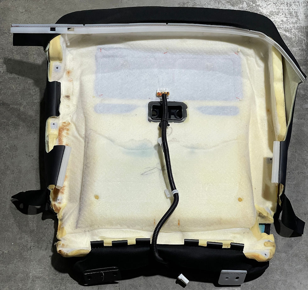
The foam turned out to be adhered directly to the back of the leather, glued on rather than sitting loose against it the way we'd assumed going in. We didn't bother trying to pry the two apart once we realized that, there wasn't an obvious benefit to separating them and a real risk of tearing something in the attempt, so they came off together as a single piece. Worth knowing if you're doing this yourself: don't go looking for a way to separate leather from foam on this seat, because as far as we can tell there isn't a clean way to do it, and the factory clearly didn't design it to be separated later.
The crossmember

With the leather and foam out of the way, the crossmember comes out next, positioned roughly behind the knee when you're seated. It's held in with 12mm bolts.
The pressure pad
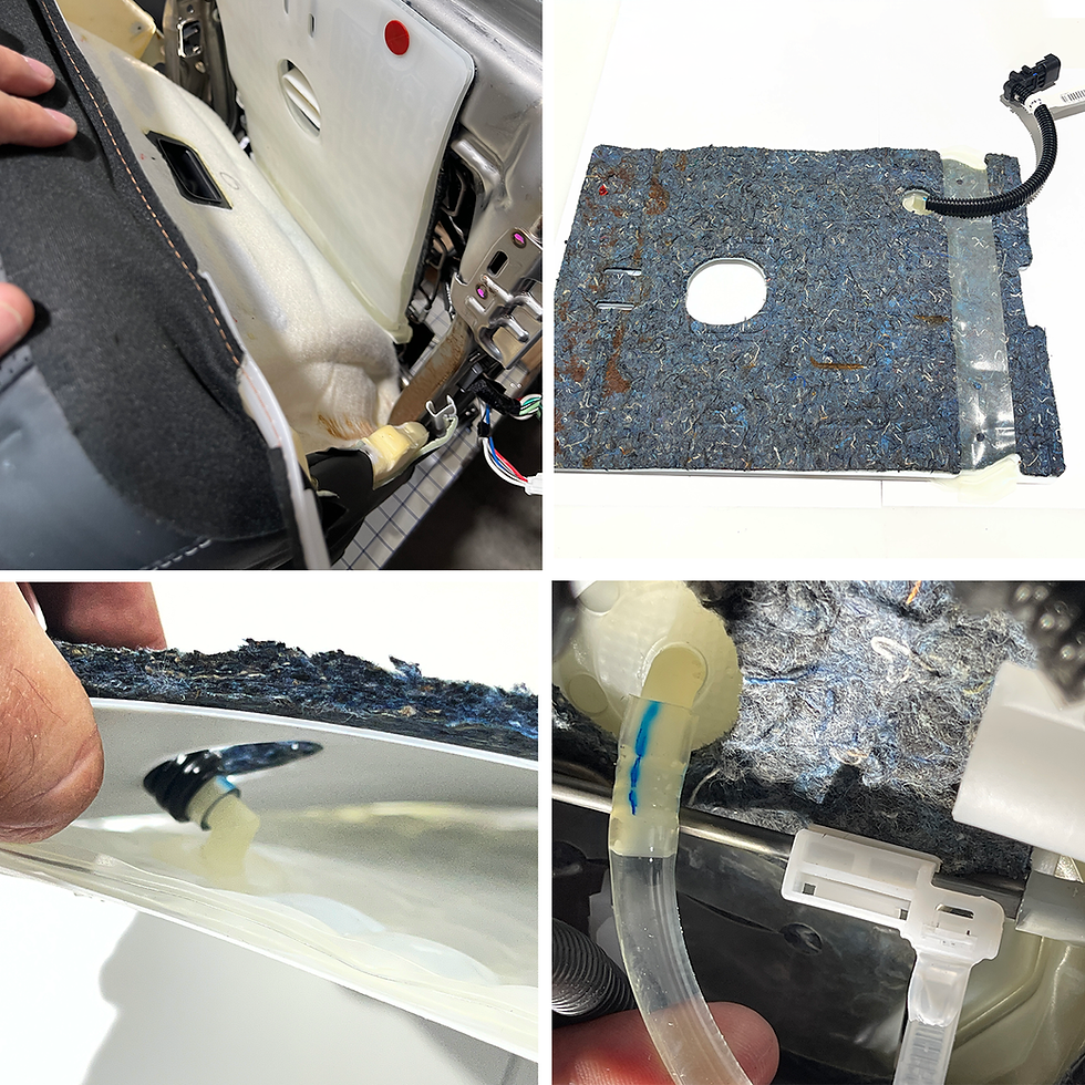
What's left exposed at this point is the pressure pad for the OCS system, the sensor responsible for telling the truck whether there's a person actually sitting in the seat. It's not an obvious thing to spot the first time you get this far into the cushion, because it's sandwiched between padding and two plastic sheets, and at a glance it can look like just another layer of cushioning rather than a discrete electrical component. Overall it measures roughly 12 by 15 inches. Two red plastic clips hold the whole pad assembly in place, nothing more elaborate than that, and the venting duct runs right through the center of it. The plastic sheets are there are anti-friction pads and to prevent damage to the pressure pad.
The pad itself is connected by a length of tubing to a separate hydraulic pressure sensor, and that connection has to be disconnected, not come apart along with the pad. There's liquid inside that tubing, and we genuinely don't know yet whether it's mineral oil or glycerine or something else. What we do know, and what matters more in the short term, is that this entire assembly should not be disassembled any further than necessary to get it out of the seat. Leave the pad exactly as it is, tubing intact, and do not open that tubing for any reason. Whatever's inside is doing a specific job in a sealed system, and there's no upside to finding out what it looks like outside of that system.
This pad is also a good example of why this whole teardown matters beyond just curiosity about how Toyota built the seat. It's one of the sensors that's actually meant to carry forward into the new build, not something we're documenting purely for the historical record. The whole pad, tubing and sensor intact, is what would end up installed underneath the Vario F seat padding down the line, either by the end-user themselves or shipped off to scheel-mann to be installed there directly. So the care being taken with it here isn't just about respecting someone else's truck parts while they sit on our bench. It's about keeping a functional component functional long enough to actually get used in the finished product.
Spring cradle

Next is the spring cradle itself, the wire assembly that actually forms the cradle underneath everything we've removed so far, rather than some separate structure. It's not bolted or screwed to the frame the way you might expect a structural component like this to be. It's held on with wire clips instead, and once those are cut or released, the cradle comes free without much resistance. One of the plastic sheets under the pressure pad sits on this piece.
Connectors along the way
We didn't tackle the connectors in this section as a separate, tidy stage of their own, set apart from the rest of the disassembly. They got dealt with as they came up, whenever a given step happened to expose one, rather than all at once at a single predictable point in the sequence.
One of those connectors is worth calling out specifically, because it's the kind of find that actually moves this project forward rather than just adding another entry to a list.
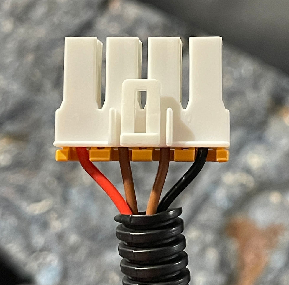
The seat heater control computer turns out to be the same unit used in the 5th Gen 4Runner, which lines up with the connector match we'd already flagged earlier in the electrical documentation. For the kit, the 4-pin white and orange connector coming off it needs to be cut and kept as a pigtail, so it can be reused on the replacement harness built for the new seat, rather than discarded with the rest of the harness going to the seat leather and heater pad.

Another one worth flagging here, the position/proximity sensor that Toyota typically only fits to the driver's seat showed up on both seats on this LX570. Across other Toyota platforms, that sensor is usually a driver-only part, there's no obvious reason to put it on the passenger side if nothing over there needs to know seat position. But at least on this 2021 LX570, it's present on both. We don't have a clear explanation for why.
The "wall"
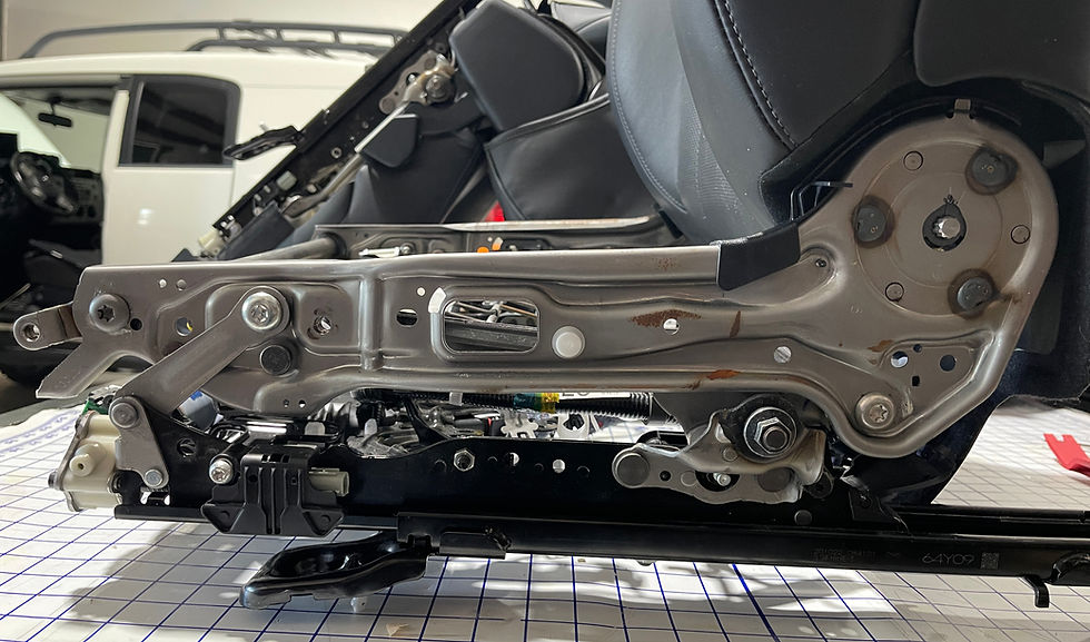
And that's where the seat bottom teardown stops, at least for now. What comes next is the seatback, and getting into it means drilling out rivets, which is a different category of work entirely from anything described above. We're not there yet, and honestly, the idea of drilling into a factory seat frame is not something any of us is looking forward to. There's a real difference between cutting wire clips and releasing wire clips designed to be released, and drilling into a structural frame that was never meant to come back apart. It's the kind of step that makes you want to find one more thing to double check first, one more photo to take, one more measurement to confirm, anything to put off committing to the drill for just a little longer. In a word "procrastination".
So that's where we'll pick up in Part 3, once we've actually worked up to it. For now, the seat bottom is fully documented, the OCS pad turned out to be more involved than it first looked when we opened the cushion. The seatback, and the rivets, are next.



Comments